All posts by Adam Goerdt

Display Bookcase

My wife wanted a display bookcase for our daughter.  She sketched a rough design out on a small piece of paper and asked if I could build it.  Obviously I said that I could.  We previously purchased a birch veneered dresser from Ikea and wanted the bookcase to match the style.  I decided to build the entire case out of birch faced plywood and finish the edges with Band-It.  I took a couple of hours and drew up some plans based on my wife’s design.  I sketched out a cut-list and was able to do the entire project from a single 4×8 sheet of plywood from Home Depot.  Total cost for the plywood, veneer and varnish was around $75.

Cut List

  • 2 – 15″x34.5″
  • 2 – 15″x31″
  • 2 – 15″x15″
  • 2 – 3.5″x34.5″
  • 3 – 6.5″x34.5″

It shouldn’t surprise anyone to know that the plywood found at Home Depot is not top quality.  One face had a very smooth and defect free veneer but the other face wasn’t sanded as smooth and contained some blemishes.  I planned the cuts as best I could to remove them, but some defects escaped.  Most of the remaining problems I was able to hide by arranging the boards on the bottom/underside of shelves but there were a couple of problems which I couldn’t find a way to hide.

All Cuts Complete


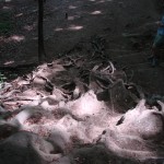
I built a simple doweling jig from scrap plywood (as the number of dowels I drilled increased the amount of wiggle in the jig increased but not so much that any of the dowels didn’t fit properly).   I drilled the dowel holes into the shelves and used a dowel center to mark the corresponding hole on the vertical.  This was an iterative process; the picture below shows the halfway point.

Making Dowel Holes


After all of the dowel holes were drilled I tried a dry fit to verify that everything was in the proper place.  I noticed that the sides of the two 15″x34.5″ shelves were not perfectly straight due to the problem I described earlier, so I made a note to fix them.

Dry Fit


During the dry fit I drew a curve line on the two uprights outside of the shelf verticals.  I used a handheld scroll saw to cut the curve and found a big gap in the plywood right under the veneer.  The veneer did not like being cut with nothing below it.

Plywood defect found when rounding the side panel


No worries, though, I’d left about a 1/8″ gap between where I cut and the line so it wasn’t going to affect anything after I filled it in.  I wanted the curves on the uprights to be identical so I clamped them together and went along the curve with 80 grit sandpaper attached to the random orbital sander. The handheld scroll saw that I used didn’t cut a 90° angle so I kept checking the angle with a square and sanded until it was 90° along the length of the curve.

View of the plywood defect after wood filler and banding applied


At this point all of the boards were in their final shape.  I took the Band-It around all of the visible edges and trimmed of the excess.  I couldn’t be happier with the way the boards looked after the edging.  Even I couldn’t tell that it wasn’t solid wood.

Back boards with edge banding


Once the edging was complete I applied the varnish.  I first tried Minwax oil based poly on a scrap piece but it yellowed the wood and didn’t match the Ikea dresser.  I bought a can of Minwax water based poly and after testing on a different piece of scrap decided that was as good as it was going to get.  The water based poly dries fast. I worked from left to right applying the poly, and even on the smaller boards the varnish was dry to the touch on the left side by the time I reached the right side.


The glue-up was done in two stages: First the center uprights were glued to the bottom and middle shelves.  The uprights and shelf-back are pinned with unglued dowels in an unsuccessful attempt to make sure the center uprights were square.  After a lot of wrangling trying to get the center uprights square with the shelves I got the bright idea in my head to clamp a square down.  I wish I would have thought of that earlier.  I also realized that two clamps really wasn’t enough for gluing the two center uprights, and was woefully inadequate for the next second where I’d be gluing all of the shelves and backboards to the two uprights.

Gluing base, center uprights and bottom shelf

The second phase was gluing the side panel to the shelves. It took a little bit of time to get all the dowels into their respective holes but everything fit together as expected.

Gluing side panels to backboards and bottom section

After the glue was dry I tacked on a piece of 1/8″ hardboard to the bottom section and called the project complete

Project Complete
Populated

Wood Calculators

I had a question about the possibility of shelf sag for a cabinet I’m planning and was pointed to this fantastic Sag Calculator which returns a result based on the material, thickness, length and width of the material.

Another useful calculator which I’d come across previously is the Wood Movement Calculator which takes similar inputs and returns the amount of expansion or shrinkage you should expect as humidity changes through the seasons.

Zenith Project

I’ve always loved the way old radios look, especially the older Zenith radios, and have wanted one for a while to act as a case for a media center PC.  My wife was browsing Craigslist one night and managed to find an old Zenith for ~$60.  We immediately jumped in the car, bought it, and brought it home.

This particular model is a 7-S-582 and was first assembled in 1942 at the Zenith factory in Chicago.  The 7 means that it’s a 7 tube radio and came with a 4-band tuner and a cabinet which contained a 78 rpm turntable.  Both the radio and phonograph were completely inoperational.

Original phonograph


Radio chassis


Underside of chassis showing old capacitors and resistors


Underside of chassis showing input source toggle switch

If you look closely at the underside of the chassis you’ll see there is a mix of cloth-wrapped and rubber wiring in the chassis.  At 70 years old the cloth-wrapped wires are still in perfect condition.  The rubber wires, however, had decayed to the point where there were potential short-circuits everywhere.  I didn’t even attempt to power it on for fear of blowing a tube or transformer or starting a fire.

The cabinet had a lot of wear on it and had a lot of dings and scrapes where the bare wood shone through the finish.  I found a Minwax stain pen in a similar color to the original stain and basically colored in the scratches.  I didn’t apply any new finish to the scratches, so the while the old dings don’t stand out at a glance they are still visible in the right light:

Re-stained side panel

The doors that housed the phono cabinet were in pretty poor shape and contained a number of deep gouges. These were completely refinished:

Original door


Refinished doors

The face of the doors has a 1/16″ veneer.  I carefully sanded off the old finish and smoothed out the scratches.  I then applied a couple of coats of lacquer to match the original finish and ended up with a beautiful result.  The photo above shows one of the remaining scratches to the left of the doors.  The scratch cuts through what’s called a ‘photo finish’, which looks to be a wood-grain print which is applied to the cabinet and not a true veneer.  I’ve been thinking about getting a true veneer and applying it to both sides but haven’t done so yet so the scars remain on the cabinet.

While doing the cabinet restore the thought entered my head to do a full restore and repair the radio as well.  The phono was completely trashed as it was missing components and the gears were threaded, so I discarded it but decided to leverage the input as an AUX connection.  After a little (ok, a lot) of googling I found a schematic for this particular model and built a parts inventory.  In addition to needing new wiring, capacitors and resistors, one of the 7 original tubes was obviously broken.  The website Antique Electronic Supply was stocked with everything I needed, so I ordered a new tube and all of the capacitors and resistors that needed replacing.  Once everything arrived I began the task of re-soldering the decayed wires and replacing the old capacitors.  I got through about 4 wires and two capacitors before deciding that this type of work was best left to a professional.  I shipped the chassis off to an expert in Ohio and received a working radio about 3 weeks later.  In the mean time I took the old interface to the phonograph and replaced it with an 1/8″ mini jack.  After the radio was returned I reinstalled it in the cabinet and connected it to my iPod. I turned them both on and heard music pouring out of the 70 year old speaker.  I’ve since installed a complete PC in the cabinet where the phonograph was originally.

Finished!
View with media PC